Editor Note: ‘Behind-the Scene’ is a new segment here at InEarMatters.net that allows the innovators and engineers to tell us the story of their audio creation – from its conception, its goal, the research and development process to its fruition, and most importantly, they are told from the prospective of the creator but not through the mouth of the PR. While this is the first and only article of the series, I do hope that, in time, more manufacturers and their engineers can step up and come forth to tell us the story of their projects and products. It is about sharing the passions for audio, not selling it.
A few months ago I was contacted by Sead Smailagic, who is working for Sony Mobile as an audio designer / engineer, regarding possible review of some of the products that he has helped to develop. One of which is the recently reviewed MH1. As he had tried to explain some of the background story and engineering theory about this headset, I thought it would be great for him, as a real person who are actually involved in the research and development of a real product, to come out from behind the scene and tell you the story himself as a contributing author of my blog. Without further ado, here it is:-
*This article is available in PDF format and can be downloaded here. Due to the limitation of the website, you are recommended to download the PDF copy for larger view of all the graphs
----------------------------------
[UPDATE Nov, 6th 2012]
Introduction:
I’m glad to be able to share part of our story behind the MH1 research and development. Hopefully you will find it interesting to find out more on our research and development work, what we do, how we do it and why we do it, as well as also find it useful to learn more about IEMs in general!
Vision
The idea behind the MH1 was to create an outstanding audio experience with a great dynamic impression that will simply turn the listener on, while still delivering that sweet balance and clarity so that even smallest details shine thru. Basically “the sound” balanced in that way to fit as many people and music genres as possible!
Defining subjective target is one thing, however designing IEMs to reach that goal is a bumpy road full of challenges! The most fundamental issue is that we all experience IEMs differently, especially in the high frequency range due differently sized and shaped heads, ears, and ear canals. At the same time, the frequency response of an IEM has large effect on perceived sound quality and is therefore an essential component of high quality IEM design! So, measuring IEMs and understand how these curves correlates with your perception doesn’t seem to be simple task.
Let’s start with some basics:
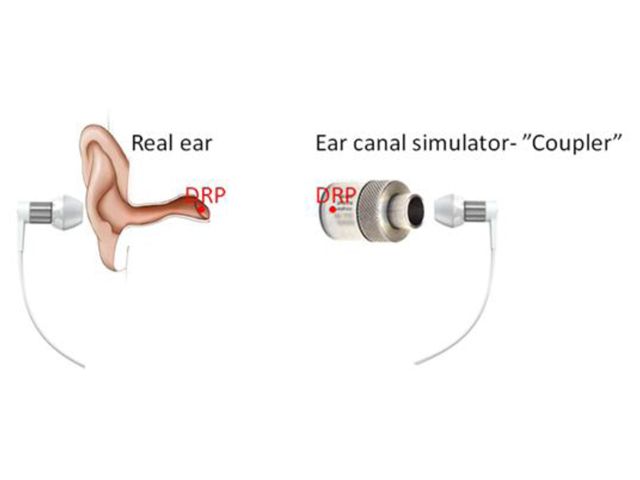
Measurement of the IEMs is normally performed using an artificial ear canal simulator – a “coupler”, as seen in the figure below. This coupler represents the average properties of the human ear canal and eardrum impedance, and frequency response here is referred to drum reference point (DRP). These couplers are fairly accurate up to ~7kHz range, however above that, uncertainty is introduced due high individual variation of the ear canal anatomy. Despite that, measurements performed via a coupler can still be useful to for full audible range analysis of IEM’s, as we will see later.
Ok, so we can use the coupler to perform measurements on IEMs, that’s great! But what shall the frequency response look like in order to provide a great audio experience and a natural balance for as many people as possible?
Searching for the target:
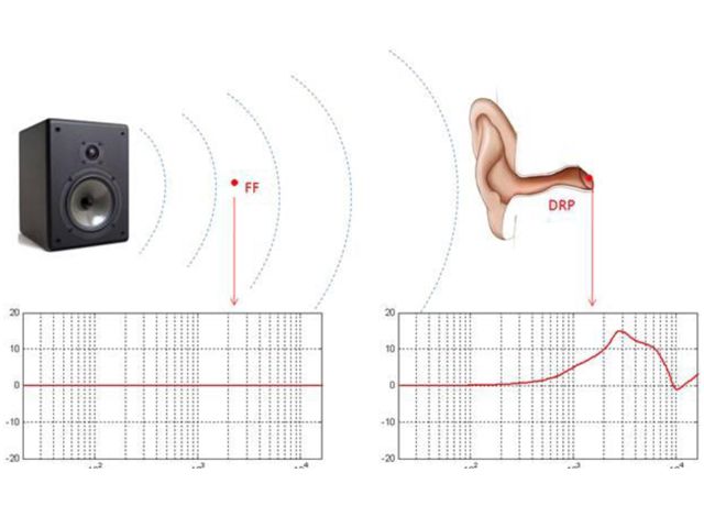
Like we mentioned, the outer ear, ear canal, head and body will have impact on the measured frequency response. Thus originally flat response in the free field (FF) will not be flat at drum reference point (DRP).
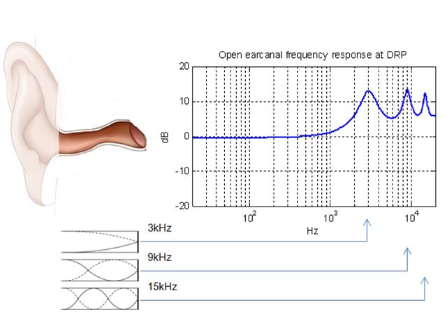
Let’s take some closer look at our ears transfer functions (TFs). In normal listening conditions our ear canal is open and this system will cause quarter wave resonances. For an average human ear these resonances will occur at approx 3k, 9k, 15k, as can be illustrated on figure below.
The outer ear, due its physical shape will effectively amplify frequencies in the range of 3k-7k. Exact shape will depend on the sound input direction.
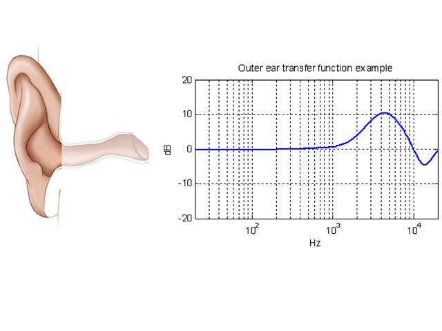
By analyzing and adding together these natural ear amplifications (HRTFs) for different directions a smooth curve can be obtained. This approach results in a curve that can be seen as a target for neutral sound reproduction. However, if headphones were tuned to provide this curve, they will still not sound very natural! In order to obtain a curve that represents more natural balance we need to consider a few more parameters from the real life. I will just mention them briefly without going into too much detail:
- Majority of the music is normally mastered to sounds good at your home hi-fi system, car, small boom-boxes…etc. Let’s now suppose that frequency response is perfectly flat on your hi-end speakers when measured in an anechoic room. Putting these loudspeakers inside the normal living room will lead to frequency response being anything else but flat. Most loudspeakers due their physical nature will not uniformly distribute energy across its working frequency range. Low frequencies will be widely spread, while treble part being more directional. In other words perceived frequency response of the loudspeakers in the room is based on the direct sound + bunch of early reflections, sometimes even referred as a power response.
- Tactile sensation of the low frequencies is missing when using headphones.
- Natural crossover between ears is missing.
- Transfer function of blocked ear differs from transfer function of open ear. As ear canal will get blocked by IEMs its properties changes from opened quarter wave pipe to a small pressure chamber with half wave resonances. Besides influence in the high frequency range (which can be seen as an IEM design concern) , it also contribute to sensitivity change and masking effects in low frequency range compared to normal opened ear canal conditions.
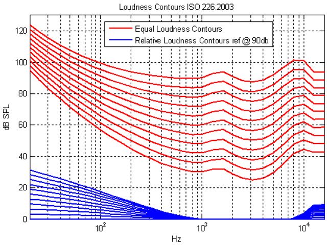
Further…If we take a closer look into our hearing mechanism we will find out that human hearing is not really linear! Perceived intensity between various frequencies will vary with absolute SPL, especially in the low- and partly in high frequency range according to loudness curves showed below… hmmm, can we say that a linear frequency response is just a relative term for humans? Anyhow, by using this knowledge, applying a suitable relative loudness curve into IEMs design can be seen as a SPL shift while maintaining impression of the same frequency balance!
After we’ve mix together all information above, it’s finally time for subjective tuning and evaluations…Let’s face it, the hearing is an extremely advanced mechanism that cannot be fully substituted by measurement equipment like microphones and head and torso simulators. Firstly, target curve candidates are tuned by “golden ears”! This step is performed using DSP and suitable IEMs, where signal processing is used to mimic and adapt to any desired response. Then final target curve is extracted by subjective evaluations performed on people with various music interests, from producers and musicians to normal average consumers.
So below we have a short summery and a few comments on our target frequency curves!
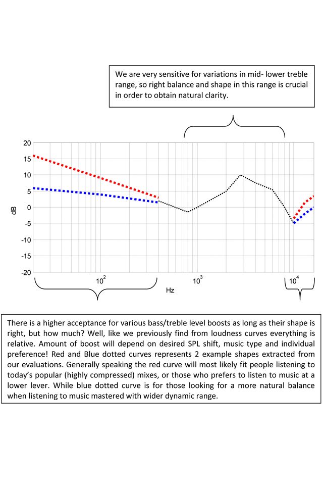
Defining the target take us one step closer on the way to “perfect” IEM design. Now it’s time to mention a few words related to development process of MH1 IEMs, let’s go through some challenges involved here!
Shaping MH1
An important parameter in IEM design that deserves attention is ergonomic. If IEMs doesn’t fit your ear canal well, you’ll simply loose all bass and audio experience will be poor. In MH1 target was to get earpieces smaller and more flexible so that they fit more people. So we’ve reduced diameter of the housing in attempt to remove interference with the outer ear. The ear cushion is made more flexible by extending its length, updating its shape and mixing two different material densities, “hybrid- type”. The core is made with more rigid material in order to maintain original tube shape and prevent leakage while outer part is softer for a more comfortable coupling and wearing.
As miniaturization was in focus, for MH1 we have developed a new generation of micro driver units measuring only 5.8mm. As size of the driver decreases, dynamic properties becomes a serious challenge. MH1 micro driver features a 4 layer voice coil, an incredibly small voice coil gap and a relatively large high density neodymium magnet for increased efficiency. Ultra wide bandwidth is secured thanks to small, light, but relativity rigid diaphragm measuring only 6um in thickness.
Ok, now we have suitable driver with high dynamics and wide bandwidth, so let’s do some tuning.
When tuning IEM’s there are quite many parameters that an audio designer can play with. Parts of the MH1 tuning are performed directly on the driver, i.e. tuning resonances and setting overall balance. Other parts are related to the IEMs back/front housing and ear cushion, controlling the shape of bass, mids and high frequencies. In MH1 sound tube is treated with various dampers, with these we can control tube- and ear canal resonances. So in order to control these, combination of acoustic foam inside the tube and acoustic mesh on top of the tube is used. This method unfortunately reduces overall sensitivity but in mine opinion it is the price you need to pay in order to extract high definition treble quality! During tuning procedure target frequency response is used as a guideline. Final touch is always performed by subjective evaluations in order to iterate an optimal balance between sound quality and design limitations.
Measurements and perception
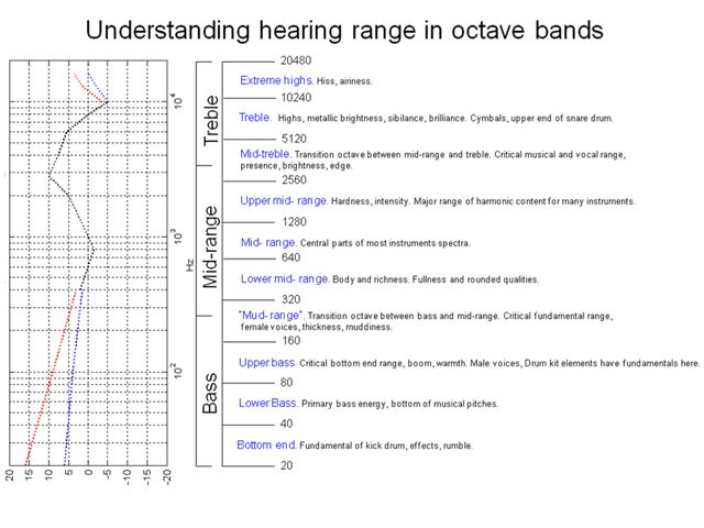
Before we start analyzing IEM’s frequency response I would recommend taking a look at the graph below. In this graph audible range is presented and sliced into octave bands. Each of these bands is categorized according to its acoustical and musical qualities and can be a very helpful tool when trying to describe what you hear in terms of frequency range.
*Click for larger picture
Like we mentioned before, using a coupler is fairly accurate up to upper midrange, and above that the frequency response and treble perception will be highly dependent upon the shape of the users’ ear canals. So, how should we interpret these measurements in the treble area? Well considering “micro” level analysis, generally speaking we could say that the frequency response shall be as smooth as possible and the number of peaks and dips shall be kept at a minimum. High amplitude variation between dips and peeks is an indication of a highly resonant design in the treble area, which will have a negative effect on the overall quality and resolution (see example1 below). Keep in mind that our ear/brain is more sensitive to peeks, while being more tolerant to dips in the spectra! When considering overall balance or “macro”- level analysis, it can instead be helpful to look at an octave averaging (refer to “Power Response” in measurements graphs), resulting in a smoother curve presentation over the entire frequency range.
Let’s go through some examples, following frequency and impulse responses are from IEM’s that are relatively common on the market today and are used here for the case study only. In these examples I would like to focus mostly on the treble area, as this is the part that is most difficult to interpret by looking at the measurements.
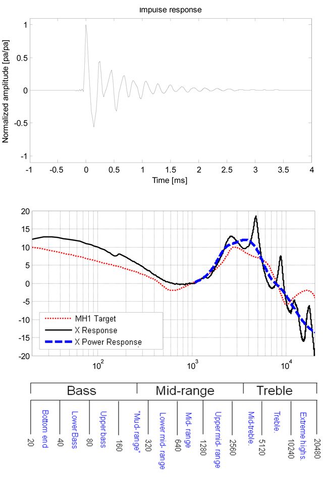
Example1. In the figure below impulse response indicates ringing. This ringing is related to a sharp resonance that can be seen in the “X” frequency response at ~5kHz. Relative intensity between 5kHz peek and 7kHz dip is almost 20dB! This will have an impact on the treble quality and give it a harsh or metallic signature. For some people this kind of resonances can at the first sight give an impression of treble sparkle, but after relatively short time will most likely lead to listening fatigue. Overall shape is tilted, bass oriented rather than well balanced, lower parts are exaggerated comparing to highs. Mids do have fairly good shape with some tendency towards V-shape given it extra crunch or attack, but again mid- treble is simply too resonant and overshadows the “real treble” and leads to overall poor perceived resolution and loss of detail.
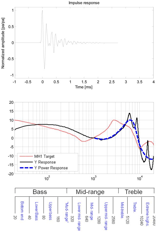
Example 2. In this one we also have some ringing that can be referred to mid-treble area. Lower end lacks real bottom and it’s dominated by upper-bass and mud-range which bleeds into the lower midrange and overshadows important musical range. Further, mids are behind, while mid-treble is peaky, leading to kind of a hollow and metallic- sibilant signature. Warning for sharp “sss” sounds, especially considering female vocals! When it comes to upper treble, it is simply masked by exaggerated low treble, so we should not expect much air or detail.
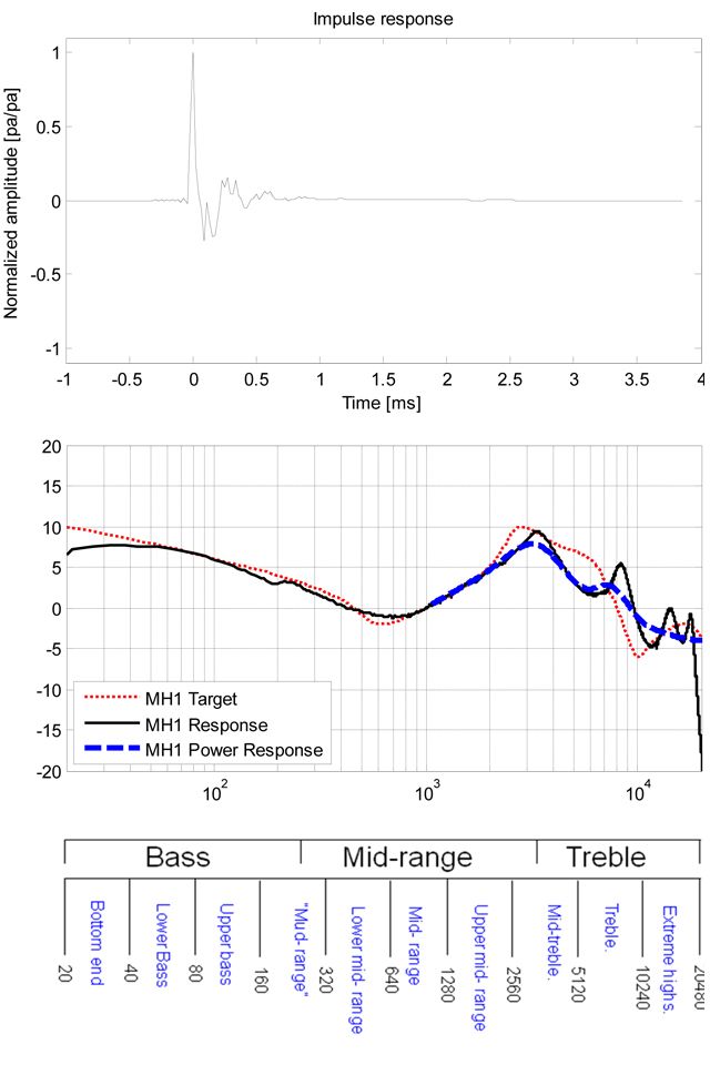
MH1 Impulse and frequency response
Well, finally here it is. I don’t intend to go though the sound analysis of MH1, instead I leave that action to the reader and reviewer.
Final word:
Designing listening experience is not an easy task! I’ve touched upon some of parameters I personally believe are important to consider when designing great sounding IEMs. However there is no such thing as perfect sounding IEM’s, we are all unique and need to choose IEM’s according to our own taste and preferences. So, in addition I’ve made some attempts to provide guidelines on how IEM’s measurements data can be interpreted in order to estimate its sound character. Unfortunately, as it comes to the specifications, there is very little relevant info related to the IEMs sound quality. In other words, there is no guaranty that an IEM with a wide frequency response i.e. 10Hz-40kHz will sound better compared to other one i.e. 40Hz-16000kHz, more is not always better! Still, hearing is believing and that’s the best way to protect yourself against marketing bias. After all, what we hear is what matters… and indeed, In-Ear matters!
A few months ago I was contacted by Sead Smailagic, who is working for Sony Mobile as an audio designer / engineer, regarding possible review of some of the products that he has helped to develop. One of which is the recently reviewed MH1. As he had tried to explain some of the background story and engineering theory about this headset, I thought it would be great for him, as a real person who are actually involved in the research and development of a real product, to come out from behind the scene and tell you the story himself as a contributing author of my blog. Without further ado, here it is:-
*This article is available in PDF format and can be downloaded here. Due to the limitation of the website, you are recommended to download the PDF copy for larger view of all the graphs
----------------------------------
[UPDATE Nov, 6th 2012]
Editor
Note: From time to time, I'll get called out as a shill. As an reviewer
in an online world that is so full of fake writers, this does come with
the territory. Instead of getting angry, I have learned to be in peace
with myself and accept the fact that I can't prove to everyone or anyone
that my intention is pure in an online world - and so, you must be your
own judge on whether I can be trusted or not.
Anyway, here is an article by another blogger that is pointing his/her finger at me, and argue that this article is 'commercially oriented excuses to sell a product". As I said, you be the judge - LINK.
~ Tai / ClieOS
----------------------------------
----------------------------------
Introduction:
I’m glad to be able to share part of our story behind the MH1 research and development. Hopefully you will find it interesting to find out more on our research and development work, what we do, how we do it and why we do it, as well as also find it useful to learn more about IEMs in general!
Vision
The idea behind the MH1 was to create an outstanding audio experience with a great dynamic impression that will simply turn the listener on, while still delivering that sweet balance and clarity so that even smallest details shine thru. Basically “the sound” balanced in that way to fit as many people and music genres as possible!
Defining subjective target is one thing, however designing IEMs to reach that goal is a bumpy road full of challenges! The most fundamental issue is that we all experience IEMs differently, especially in the high frequency range due differently sized and shaped heads, ears, and ear canals. At the same time, the frequency response of an IEM has large effect on perceived sound quality and is therefore an essential component of high quality IEM design! So, measuring IEMs and understand how these curves correlates with your perception doesn’t seem to be simple task.
Let’s start with some basics:
Measurement of the IEMs is normally performed using an artificial ear canal simulator – a “coupler”, as seen in the figure below. This coupler represents the average properties of the human ear canal and eardrum impedance, and frequency response here is referred to drum reference point (DRP). These couplers are fairly accurate up to ~7kHz range, however above that, uncertainty is introduced due high individual variation of the ear canal anatomy. Despite that, measurements performed via a coupler can still be useful to for full audible range analysis of IEM’s, as we will see later.

Ok, so we can use the coupler to perform measurements on IEMs, that’s great! But what shall the frequency response look like in order to provide a great audio experience and a natural balance for as many people as possible?
Searching for the target:
Like we mentioned, the outer ear, ear canal, head and body will have impact on the measured frequency response. Thus originally flat response in the free field (FF) will not be flat at drum reference point (DRP).

Let’s take some closer look at our ears transfer functions (TFs). In normal listening conditions our ear canal is open and this system will cause quarter wave resonances. For an average human ear these resonances will occur at approx 3k, 9k, 15k, as can be illustrated on figure below.

The outer ear, due its physical shape will effectively amplify frequencies in the range of 3k-7k. Exact shape will depend on the sound input direction.

By analyzing and adding together these natural ear amplifications (HRTFs) for different directions a smooth curve can be obtained. This approach results in a curve that can be seen as a target for neutral sound reproduction. However, if headphones were tuned to provide this curve, they will still not sound very natural! In order to obtain a curve that represents more natural balance we need to consider a few more parameters from the real life. I will just mention them briefly without going into too much detail:
- Majority of the music is normally mastered to sounds good at your home hi-fi system, car, small boom-boxes…etc. Let’s now suppose that frequency response is perfectly flat on your hi-end speakers when measured in an anechoic room. Putting these loudspeakers inside the normal living room will lead to frequency response being anything else but flat. Most loudspeakers due their physical nature will not uniformly distribute energy across its working frequency range. Low frequencies will be widely spread, while treble part being more directional. In other words perceived frequency response of the loudspeakers in the room is based on the direct sound + bunch of early reflections, sometimes even referred as a power response.
- Tactile sensation of the low frequencies is missing when using headphones.
- Natural crossover between ears is missing.
- Transfer function of blocked ear differs from transfer function of open ear. As ear canal will get blocked by IEMs its properties changes from opened quarter wave pipe to a small pressure chamber with half wave resonances. Besides influence in the high frequency range (which can be seen as an IEM design concern) , it also contribute to sensitivity change and masking effects in low frequency range compared to normal opened ear canal conditions.
Further…If we take a closer look into our hearing mechanism we will find out that human hearing is not really linear! Perceived intensity between various frequencies will vary with absolute SPL, especially in the low- and partly in high frequency range according to loudness curves showed below… hmmm, can we say that a linear frequency response is just a relative term for humans? Anyhow, by using this knowledge, applying a suitable relative loudness curve into IEMs design can be seen as a SPL shift while maintaining impression of the same frequency balance!

After we’ve mix together all information above, it’s finally time for subjective tuning and evaluations…Let’s face it, the hearing is an extremely advanced mechanism that cannot be fully substituted by measurement equipment like microphones and head and torso simulators. Firstly, target curve candidates are tuned by “golden ears”! This step is performed using DSP and suitable IEMs, where signal processing is used to mimic and adapt to any desired response. Then final target curve is extracted by subjective evaluations performed on people with various music interests, from producers and musicians to normal average consumers.
So below we have a short summery and a few comments on our target frequency curves!

Defining the target take us one step closer on the way to “perfect” IEM design. Now it’s time to mention a few words related to development process of MH1 IEMs, let’s go through some challenges involved here!
Shaping MH1
An important parameter in IEM design that deserves attention is ergonomic. If IEMs doesn’t fit your ear canal well, you’ll simply loose all bass and audio experience will be poor. In MH1 target was to get earpieces smaller and more flexible so that they fit more people. So we’ve reduced diameter of the housing in attempt to remove interference with the outer ear. The ear cushion is made more flexible by extending its length, updating its shape and mixing two different material densities, “hybrid- type”. The core is made with more rigid material in order to maintain original tube shape and prevent leakage while outer part is softer for a more comfortable coupling and wearing.
As miniaturization was in focus, for MH1 we have developed a new generation of micro driver units measuring only 5.8mm. As size of the driver decreases, dynamic properties becomes a serious challenge. MH1 micro driver features a 4 layer voice coil, an incredibly small voice coil gap and a relatively large high density neodymium magnet for increased efficiency. Ultra wide bandwidth is secured thanks to small, light, but relativity rigid diaphragm measuring only 6um in thickness.
Ok, now we have suitable driver with high dynamics and wide bandwidth, so let’s do some tuning.
When tuning IEM’s there are quite many parameters that an audio designer can play with. Parts of the MH1 tuning are performed directly on the driver, i.e. tuning resonances and setting overall balance. Other parts are related to the IEMs back/front housing and ear cushion, controlling the shape of bass, mids and high frequencies. In MH1 sound tube is treated with various dampers, with these we can control tube- and ear canal resonances. So in order to control these, combination of acoustic foam inside the tube and acoustic mesh on top of the tube is used. This method unfortunately reduces overall sensitivity but in mine opinion it is the price you need to pay in order to extract high definition treble quality! During tuning procedure target frequency response is used as a guideline. Final touch is always performed by subjective evaluations in order to iterate an optimal balance between sound quality and design limitations.

Measurements and perception
Before we start analyzing IEM’s frequency response I would recommend taking a look at the graph below. In this graph audible range is presented and sliced into octave bands. Each of these bands is categorized according to its acoustical and musical qualities and can be a very helpful tool when trying to describe what you hear in terms of frequency range.

*Click for larger picture
Like we mentioned before, using a coupler is fairly accurate up to upper midrange, and above that the frequency response and treble perception will be highly dependent upon the shape of the users’ ear canals. So, how should we interpret these measurements in the treble area? Well considering “micro” level analysis, generally speaking we could say that the frequency response shall be as smooth as possible and the number of peaks and dips shall be kept at a minimum. High amplitude variation between dips and peeks is an indication of a highly resonant design in the treble area, which will have a negative effect on the overall quality and resolution (see example1 below). Keep in mind that our ear/brain is more sensitive to peeks, while being more tolerant to dips in the spectra! When considering overall balance or “macro”- level analysis, it can instead be helpful to look at an octave averaging (refer to “Power Response” in measurements graphs), resulting in a smoother curve presentation over the entire frequency range.
Let’s go through some examples, following frequency and impulse responses are from IEM’s that are relatively common on the market today and are used here for the case study only. In these examples I would like to focus mostly on the treble area, as this is the part that is most difficult to interpret by looking at the measurements.
Example1. In the figure below impulse response indicates ringing. This ringing is related to a sharp resonance that can be seen in the “X” frequency response at ~5kHz. Relative intensity between 5kHz peek and 7kHz dip is almost 20dB! This will have an impact on the treble quality and give it a harsh or metallic signature. For some people this kind of resonances can at the first sight give an impression of treble sparkle, but after relatively short time will most likely lead to listening fatigue. Overall shape is tilted, bass oriented rather than well balanced, lower parts are exaggerated comparing to highs. Mids do have fairly good shape with some tendency towards V-shape given it extra crunch or attack, but again mid- treble is simply too resonant and overshadows the “real treble” and leads to overall poor perceived resolution and loss of detail.

Example 2. In this one we also have some ringing that can be referred to mid-treble area. Lower end lacks real bottom and it’s dominated by upper-bass and mud-range which bleeds into the lower midrange and overshadows important musical range. Further, mids are behind, while mid-treble is peaky, leading to kind of a hollow and metallic- sibilant signature. Warning for sharp “sss” sounds, especially considering female vocals! When it comes to upper treble, it is simply masked by exaggerated low treble, so we should not expect much air or detail.

MH1 Impulse and frequency response
Well, finally here it is. I don’t intend to go though the sound analysis of MH1, instead I leave that action to the reader and reviewer.

Final word:
Designing listening experience is not an easy task! I’ve touched upon some of parameters I personally believe are important to consider when designing great sounding IEMs. However there is no such thing as perfect sounding IEM’s, we are all unique and need to choose IEM’s according to our own taste and preferences. So, in addition I’ve made some attempts to provide guidelines on how IEM’s measurements data can be interpreted in order to estimate its sound character. Unfortunately, as it comes to the specifications, there is very little relevant info related to the IEMs sound quality. In other words, there is no guaranty that an IEM with a wide frequency response i.e. 10Hz-40kHz will sound better compared to other one i.e. 40Hz-16000kHz, more is not always better! Still, hearing is believing and that’s the best way to protect yourself against marketing bias. After all, what we hear is what matters… and indeed, In-Ear matters!
Sead Smailagic
Audio & Acoustic Designer
Sony Mobile, Companion Products
